Friday, October 16, 2015

The New Cottage Lane…

The changes around the “L” Shaped House on Cottage Lane in Minnetonka are not limited to only plant life. Since we moved into the neighborhood three new homes have been built along the North side of Cottage Lane and we have new neighbors in at least two other homes.

Our annual neighborhood National Night Out party this year was blessed with the sounds of children playing, dogs barking, and friends laughing!
 
IMG_2932(2)

Rain Garden… 2015

The rain garden at the end of the driveway received some attention in the 2015 upgrades as well. We planted the rain garden in July of 2010 (see it here) and have had some attrition over the past couple of years. The plantings along the front edge (in particular) are subject to not only snowplow damage but also the ravages of Minnesota road salt. This round of new plants will probably not be the last!

IMG_4542(3)

New Trees… 2015

We lost two thirds of a very nice Hackberry along the driveway in a big wind storm this summer. As a part of the project upgrading the landscaping and plantings we decided to replace it and one White Pine along the border with our neighbor to the West that died last year. The first two photos below show the Hackberry laying in pieces on the driveway and the Tamrac we have decided to replace it with.

IMG_4451(2)   IMG_4452(2)

We placed five White Pines along the West property line in the original planting back in August 2010 (see it here). Four of the trees taken root and prospered. The tree at the top of the hill slowly withered and finally died last year. Matt found us a very nice natural tree at Gertens and placed it in the same spot.

IMG_4453(2)   IMG_4459(2)

Landscaping Before and After

In my Minnesota Native Prairie 2.0 posting just previous I stated that 60% of the plantings in and around the “L” Shaped House have come in “perfectly”. I think the before and after image below shows this nicely. The lower photo shows the area around the stairs leading to the front porch (in early 2010) just after planting the pagoda dogwood trees, the endless summer hydrangea, and various grasses (see it here). The top photo shows this same area earlier this summer (2015) at the beginning of the fourth growing season.

Amazing…

1491491_10154180430927281_5406590359691316150_o

Refreshing a Meadow…

So… Here is Matt Wolfe’s plan for the Minnesota Native Prairie 2.0 (click on image to see it huge). The highlighted areas are being replenished with 1500 new plantings of 19 different plants and grasses, two new trees are being added, and the entire grounds of the “L” Shaped House are being top dressed with pine bark mulch. We are being especially mindful to include plants in the meadow that will attract both Hummingbirds and Monarch butterflies.

We are also re-configuring the irrigation system adding two new watering heads in the highlighted areas while removing heads in the lower right hand corner that are no longer needed. It is especially cool to see that this area has grown in so well that we will no longer have to water the plants.


24x36 sheet

The project starts with the pine bark mulch top dressing. We engaged Justin Crandall Midwest Groundcover to blow-in the mulch. He and his dad showed up with his amazing truck and spent two days blowing  90 cubic yards of their pine bark mulch. The whole neighborhood smelled like a pine forest for two days after they finished!

IMG_4074(2)

Matt and his crew form Lee’s Landscape came in right behind the mulching operation to start installing the new plants in the meadow.  Some of the “flats” containing rooted plants can be seen sitting on the freshly installed mulch in the photos below.

IMG_4441(2)

IMG_4469(2)

Planting the 1500 rooted plugs in the three areas across the bottom of the front yard took two days. The two photos below show the meadow near the end of their efforts. Once they finished planting plugs an application of corn meal gluten is applied covered with a sprinkling of additional pine bark mulch. Now we all sit back and hope for a nice blanket of snow to cover everything for the winter.

IMG_4557(3)

IMG_4570(3)

Minnesota Native Prairie 2.0

After completing construction and moving into the “L” Shaped House in late 2010 we turned our attention to the yard and landscaping. From the very beginning of this big adventure we have had a master plan for the landscaping and plants (see it here). An integral part of this plan is the native Minnesota meadow extending to the street in the front yard.


24x36sheet


Now that we have seen the results of three complete growing seasons we invited Matt Wolfe back to assess the progress toward our goal of having a native prairie meadow yard and engaged him to supervise the planning and planting of  “Native Prairie Meadow 2.0” at the “L” Shaped House.

I have taken to describing the results of our original planting efforts as having been… “largely Successful”

  • 60% of the plants came in perfectly
  • 20% of the plants grew “reasonably” well
  • 20% of the plants did not make it

Unfortunately three big sections of grasses planted in the meadow region of the front yard fall into the 20% of plantings that did not make it at all. This has resulted in an especially obvious bare area right out front for the last year. Matt is convinced that a combination of more shade than expected in the front yard combined with inadequate  irrigation coverage is at the “root” of our troubles. Deb and Helen think that Phil made friends with the geese instead of chasing them away and that they ate all the sweet grass together.  No matter the cause… we are forging ahead with Minnesota Meadow 2.0!

Thursday, October 15, 2015

Rollac Rolling Shutters

The screen porch on the front of the “L” Shaped is is almost certainly the favorite space inside the “L” Shaped House. Opening the french doors to the porch in the spring transforms the living room into a wide open space that includes all the outdoors. Many gatherings at the “L” Shaped House end with everyone crowded together competing for a comfortable place to sit. The only complaint has been the late summer afternoon sun shining directly into the space.
Our friend Dave Lommen at Shutters and Shades in Hopkins suggested rolling shutters as the best possible solution to this problem. He and his crew installed the Rollac Rolling Shutters in May (2015). They are a  fantastic addition to the front porch!

IMG_0126(2)

The shutters roll up into a metal enclosure that tucks up under the porch roof overhang nicely and are operated with a wireless remote.

IMG_0140(2)        IMG_0124(3)

The rolling shutters in action!


Five Year Updates…

So… My last posting on these pages is dated June 14, 2012.

Demolition of the Danielson home started on June 22, 2009 (see it here)…

Work on the footings for the “L” Shaped House started July 7, 2009 (see it here)…

We moved in October 7, 2010 (see it here)…

As you can imagine a lot has happened in these last four to five years. Even though this blog was always intended to be only a record of the planning and building of the “L” Shaped House I’ve decided to add a series of “Five Year Updates” to help finish the story.

Anna and Grandma Ruth cooking rice pudding for the Ohnesorge Christmas party.

4G3A1214(3)

Thursday, June 14, 2012

The Ducks of Cottage Lane…

The pond across the street has produced not only Wood Duck babies but also a family of Hooded Mergansers. We have had the rare privilege of watching as these new additions thrive in the middle of the city.

A26U8149(2)

Thursday, May 31, 2012

Wood Ducks…

Anna and I have built and erected two wood duck houses on the shoreline of the pond across the street. The ducks have enthusiastically adopted the houses and we have the second brood of the year exploring the pond.

Wood Duck Brood (small)

One of the houses along the North shore…

Wood Duck House

Google Maps…

Google Maps has just recently been update and the “L” Shaped House now shows up in a search of the neighborhood. I don’t know.. it looks kind of big.

Google Maps 1

Google Maps 2

Monday, January 9, 2012

Concept to Finished Kitchen

In the very beginnings of the design process for the “L” Shaped House we spent considerable time planning the kitchen area. In this blog posting from February 2009 we included a photograph of a kitchen that both Deb and I found pleasing. The image below presents the concept kitchen and the very real space in a before and after format.

Design concept 2

Sunday, January 8, 2012

Interior Photos of the “L” Shaped House

After a little more than one year of living in the “L” Shaped House I’ve decided to take on a project to photograph all of the interior rooms. As the kitchen is the main gathering point in the house it makes for a fine starting point. The first photo below shows our mixer on the countertop in the back corner with the Cambria island out front.

Kitchen 2 (small)

The next photo shows the view of the island from the doorway leading to the breezeway. Here we see archways leading to both the dining area and the foyer inside the front door.

Kitchen (small)

The last photo shows the kitchen and dining area from the far corner of the dining room table. Here we can see the archways separating all of the first floor rooms in the open style Mike Kloti envisioned in the original plans.

Dining Room (small)

Monday, October 10, 2011

Autumn Images…

As Autumn arrives we are enjoying the end of the first full cycle of plant growth in and around The “L” Shaped House. In a effort to enhance this beautiful fall season Deb engaged the services of our friend Elizabeth Fischer who has a new business (Garden Junkie Designs) specializing in outdoor seasonal decorations.

IMG_1094(3)

The two photos below show Elizabeth and her husband Andrew as they work to transform our front porch with a celebration of fall colors. Their work is really unique and beautiful.

IMG_1085(2)  IMG_1123(2) 

The front of The “L” Shaped House with our tall grass landscaping is shown below.

Autumn Yard 3

The last two photos show the back yard of the house. The first shows the “no-mow” turf and landscape gardens from a spot under our neighbor’s maple tree in the front yard.

Autumn Yard 1

The last photo shows the view of the back yard from a spot just beyond the garage. The “no-mow” turf has come a long way this first growing season. These photos were taken shortly after mowing it for the very first time (huh…?). Matt Wolfe recommended mowing the back yard late this fall to promote “fuller” growth next spring and to discourage rodent (moles and voles) burrowing this winter.

We’re absolutely loving the “woodsy” feel of the backyard landscaping…

Autumn Yard 2

Friday, October 7, 2011

Accessibility Lift…Design Process

The design for wheelchair lift in the “L” Shaped House is the result of a carefully considered engineering effort. The first phase of this effort was an extensive search for a commercially available lift. I think it is almost always better to buy than build when you are looking for an item like this. The commercial builders (presumably) have the advantage of having gone through many design iterations and their products generally represent the culmination of this process. We found many examples of lift assemblies available in the marketplace. Ranging from manually actuated portable lifts all the way to elaborate built-in elevators. Unfortunately none of the commercial lifts we found would fit in the space we have available. The collage below shows some of the lifts we considered in the search. The Liftboy lifting platform from Powerlift (upper left) comes as close to meeting our requirements as any of them…but in the end all are either too big or don’t lift high enough.

Commercial Lifts

The two lifts in the image below highlight the difficulty we faced while searching for a commercial lift to fit in the space available at the end of the stairs in the garage. Lifts generally fell into two categories; they were too wide or too long. It is also surprising how expensive these sorts of lifts are (nearly $6,000 for the blue one).

lift dimensions

While searching we came across a few examples of homemade lifts. A Canadian gentleman built the lift shown below (I can’t find his link again). The very clever cantilevered design addresses many of the space considerations we face in our home. It is especially interesting because the platform could be lifted quite high without requiring a large footprint. We spent some time playing around with this compelling configuration. His implementation is kind of crude…he does not use any bearings in the vertical slide. The sketch shows some possible improvements to the slide assembly but this design (compelling as it is) has a few disadvantages related actuating and controlling the lifting platform. That is…the overhead structure supporting the pulleys and cables gets tall and implementing a safe and simple control would be a little challenging (his is just a momentary switch). Furthermore I’ve found it challenging to get motor driven cable systems to operate smoothly. We considered the possibility of using a garage door actuator but could not find a small enough version anywhere.

Cantilever Concept (arrows)

Given our reservations related to controls for our lifting mechanism we expanded our search to include some other kinds of lifts. A number manufactures build lift assemblies that incorporate linear actuators in their designs. The linear actuators used generally include all sorts of nice control features like built in limit switches and “soft start” motors. Examples of these include the many different versions of lifts used to transport electric scooters for the disabled.  Unfortunately no one makes a lift rated for wheelchairs that lifts 48”. The image below shows two examples of these sorts of lifts. The Burr Handi-Lift is an interesting example that lifts to higher heights but they specifically exclude wheelchairs.

Scooter lifts

Our search turned up a fascinating possibility in the form of a personal watercraft dock lift. Several manufactures produce these lifts with both manual and electric actuators and integrated control systems. As interesting as this seems…this kind of lift has some disadvantages. The cantilevered platform has to be pretty robust (think tall) to accommodate the load and therefore ends up sitting something like 6” off the floor in the lowered position.

Boat Lift Concept

The simplicity and (relative) low cost of the mid-rise lift I purchased from Greg Smith Equipment for the third stall in the garage compelled us to look closely at this design. These kinds of hydraulically actuated scissors lifts are very common in industrial applications. The Atlas TD6MR has more than 48” of stroke and is capable lifting 6,000 pounds. Furthermore the hydraulic control system is quiet, smooth, safe, and runs off a single 120 volt outlet.

Atlas Scissors Lift

A scaled drawing of a scissors lifting mechanism tailored to the space available clearly shows that a single set of lifting arms results in a mechanism that would be unstable in the fully raised position. I produced the sketch below to inform Dan Oss and Byron Knapp (PICo’s engineering team) as we asked some questions about the structural elements of the lift mechanism. I was specifically interested in understanding the effects of lengthening one of the lifting bars.

Scissors 2

Dan quickly produced the CAD model shown here that shows how this structure works. The unequal length arms cause the platform to rotate slightly as the lift is raised. Carefully placing pivot points in the structure results in a platform that is tilted slightly forward at the bottom and slightly backward at the top of the travel. Even with this one extended lifting arm the structure looks a little unstable at the top of its travel.

Scissors concept 1 (highlight)

Working with this model quickly exposed the advantages of a “compound” scissors arrangement. In this configuration two sets of connected lifting bars push the platform to the same height while maintaining a comfortable (stable) spread even at the top of the travel. The lower sketch shows a possible motorized lifting configuration that allows the bars to clear one another as the platform is raised.
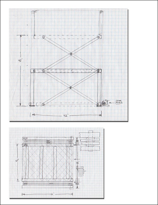
Compound Scissors Concept

As Dan’s experiments with the structure continued another possibility emerged. This time pairs of lifting arms tied together at their centers rotate and slide along a connecting rod as the stage is raised. This arrangement is superior to the previous in that the lifting bars are really quite short in relation to the stroke of the lift. It also provides for an uncluttered area between the bars for a possible actuator.

Compound Scissors Concept 2

The next sketch shows the real breakthrough in this process. Dan quickly discovered that combining a single full length lifting bar with two half length bars allowed for a structure that not only has fewer parts but also provided more flexibility for actuators. The sketches below show the mechanism as it quickly evolved. The first shows it with a full side panel supporting the arms while we see the greatly simplified support structure in the second.

Final Scissors Concept 2

The 3D CAD model below shows the lift assembly in its final form (the back side lifting mechanism is removed for clarity). Here we see the lifting platform fully raised with the hydraulic cylinder in place in the structure. The hydraulic actuator is positioned slightly off center on the lifting bar so that a cylinder with 14” of stroke produces 42” of  platform motion. The ends of the lifting bars are guided in linear slides and the cylinder is tucked snugly in-between. All of the elements in the structure are sized to provide a 1000 lb. lift rating which should easily accommodate our expected maximum 400 lb. requirement.

Final Scissors 2

We plan to use a hydraulic control system from Dalton Hydraulics. The MTE Hydraulic Pumping Station (250-730) is a D.C. powered system that we will connect to a deep-cycle battery with a “maintainer” charging system. The D.C. system will allow us to use the lift in the event we lose electrical power in the house. Multiple wired remotes will allow us to have push button control both on the platform and at the top and bottom of the lift.
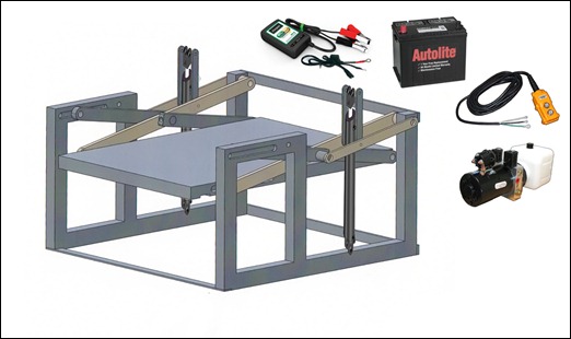
Lift with control 2

C:\AutoManager WorkSpace\BEPLEY\M-Mteserver2,D-MTE PROD\Drawing\Working Copy\399\39901194-1.dwg Model (1)

Monday, September 26, 2011

Wheelchair Lift (modeled)

Over the weekend we straightened up in the garage and re-checked dimensions in the space where the wheelchair lift will be positioned. I also placed Dan Oss’s SolidWorks 3D model in the photograph below of the newly cleaned-up area using Photoshop. Arrows in the sketch show the lift platform movement as well as the wheelchair path. I think we are all now confident that this design is going to work nicely.

The next order of business is to “tweak” the structural elements of the lift mechanism as we decide on some important properties … like the size and shape of the rectangular steel tubing, and the thickness of the lifting bars. We might even subject the model to some simple finite element analysis.

Wheelchair Lift (in place cylinders notes)

Friday, September 23, 2011

Wheelchair lift (refined design)

One day of  review and refinements has resulted in this final(?) design for the accessibility lift in the garage at the “L” Shaped house. The first sketch shows the lift with the platform raised a little less than halfway up it’s travel.

Wheelchair Lift 10 

The second sketch shows the lift platform fully extended at the top of it’s travel. The transparent platform exposes the lifting mechanism under the far side.

Wheelchair Lift 9

The last sketch shows two hydraulic cylinders (crudely) placed in the assembly for clarity.

Wheelchair Lift (cylinders)