Showing posts with label Automation. Show all posts

Friday, September 10, 2010

Home Automation…Central vacuum

The SLH Home Systems folks finished installing the Beam central vacuum system at the “L” Shaped House yesterday afternoon. The system includes the power unit in the basement, two Q Power Team head units (one on each floor), and a garage hose and tool kit. The head units have a 30’ hose with a quilted fabric hose cover to protect the walls and base boards. The photos below show the head unit for the first floor vacuum  we plan to store in the laundry room closet.

Automation 39 Automation 40

In the video below Helen demonstrates the features and operation of the central vacuum system.

Thursday, September 9, 2010

Home Automation…Day 7

Today was a really big day for the home automation and audio visual systems at the “L” Shaped House. The SLH Home Systems folks finished setting up the alarm, and central vacuum systems early this morning and spent the rest of the day mounting the big screen televisions and setting up the audio systems in the rest of the house. The first photo shows the fruits of all this work as Sam takes in our ceremonial first Blue-Ray movie screening…The Dark Knight…on the 60” plasma screen in the basement.
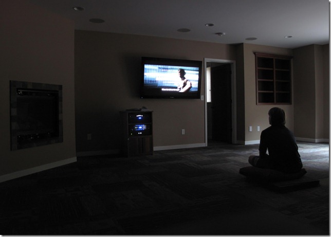
AudioVisual 5

The work began on the back wall of the garage as the SLH guys mounted the junction box in the first photo for the cable television wiring. We have not yet picked a provider for cable TV but have the wiring for either Comcast Cable or Direct TV satellite in place. The second photo shows the video amplifier and splitter in the media distribution center on the wall in the mechanical room. We have the co-axial cables running to the televisions connected to the broadcast antenna in the attic and are receiving a remarkably good signal across the channels.

AudioVisual 9 AudioVisual 11

The next photo shows the structured media box on the plywood wall panel in the mechanical room with the 19” rack on the left and the alarm system box at the top right hand side. The in-house audio system (ceiling speakers on the first floor) is connected to the stereo receiver that is installed on the bottom shelf of the 19” rack system. The receiver is connected to a set of RCA jacks in the wall along the back of the kitchen desk where a music player (ipod/Zune) or tuner may be attached to the system. The Yamaha receiver is connected to the antenna in the attic that brings in more than 40 radio stations.  We have wires running in the walls throughout the house that terminate in this area to support almost any possible contingency in the event we decide to add a more sophisticated audio control system later. The SLH guys also finished installing the last bits of the alarm system, powered it all up, and tested all the contacts, motion detectors and panels.

AudioVisual 3

The photo here shows the alarm panel inside the breezeway entrance set up ready to arm. Deb and I got a complete tour of the alarm system features and instructions on how to arm and disarm the system. Starting tonight the “L” Shaped House armed and secure!

AudioVisual 10

The sixth photo shows the Beam central vacuum power unit installed on the wall in the basement mechanical room. Deb and I also got a tour of the features and operation of the vacuum system today. The SLH guys mounted the hose racks and tool kits in the first and second floor closets and tested all of the vacuum inlets throughout the house. This whole system is going to be really slick!
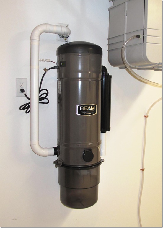
AudioVisual 8

The series of photos below show the SLH guys as they worked to install the big screens in the basement family room and first floor music room. The first shows the family room as they got started sorting out the wiring and laying out all of the elements of the A/V system.

AudioVisual 1

Next a shot of the Pioneer plasma screen as they work to prepare the wall mounting system.
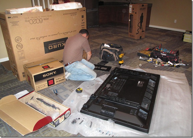
AudioVisual 2

Finally a shot of the basement family room with the plasma screen mounted on the wall under the surround sound speakers in the ceiling.

AudioVisual 4

The last two photos show the 46” Sony LCD television on the wall of the first floor music room. First one of the SLH guys working on tying up some of the extra wires behind the screen as they finish up mounting both the television and Samsung sound bar. The sound system includes speaker “bar”  beneath the television and wireless sub-woofer in the far corner of the room.

AudioVisual 6

And finally…a shot of the complete system mounted on the music room wall all ready to go!

AudioVisual 7

Saturday, August 21, 2010

Qwest phone service…Day 1

Our friends at Qwest came by this morning and connected the “L” Shaped House to their phone network. The first photo below shows the Radio Shack wall mount phone I put in the garage later this afternoon. We have a single phone line and plan to use Qwest’s (20 Mbps…DSL) “Heavy Duty” internet service.

The next photo shows the (slightly amused) Qwest guy working to install our new Network Interface Device (box) on the back wall of the garage. He was not exactly prepared to be photographed while installing a new service…but was a really good sport about it!

 Automation 36 Automation 37

Friday, August 13, 2010

Heating & A/C…Day 12

John DoBrava  (American Air Systems) and Curt Colstrom (Wire-Rite) got together to wire the two thermostats and the air exchange control at the “L” Shaped House this morning. The photo below shows the Honeywell thermostat in the back hallway on the first floor up and running. The Broan air exchange controller is shown mounted just above the thermostat on the same wall. The air exchange control can be programmed much like the heating thermostat to provide varying amounts of fresh air to the house.

Heating 35

Wednesday, August 4, 2010

Home Automation…Phone and Video

The SLH Home Systems guys were back today to finish up the cat 5 wiring and start their work on the phone and video distribution systems in the basement mechanical room. These systems will be housed in the steel enclosure installed next to the networking rack on the plywood wall panel. The first photo shows the new box mounted to the wall with the telephone and video cables routed into the top from the open ceiling above.

The next photo shows the Channel Vision phone line filter and surge protector installed in the new enclosure and the six dedicated phone lines terminated in the telecom distribution module just below.

The last photo shows the cat 5 patch panel installed in the top of the relay rack with all of the patch cables connected to the (barely visible) Netgear switch a couple of spaces below. We have 23 hard-wired (cat 5) network connections throughout the “L” Shaped House that can be used for a variety of purposes including networked computers & printers, wireless access points, or even (possibly) cat 5 video distribution.

All of the wiring associated with the home automation systems is terminated on the (plywood) panel in the mechanical room. Our goal (from the very beginning) is to have a  “future proof” system that can be easily reconfigured from this central location to almost any purpose.

Home Automation…Networking Rack (2)

The SLH Home Systems guys were out yesterday working on the networking side of our home automation system. I decided to have them punch down the cat 5 cables in the patch panel and install the switch and patch cables. The first photo below shows the  plywood panel Paul installed on the back wall of the mechanical room with the relay rack, surge suppresser outlet strip, and alarm system box all in place.

The next photo shows the relay rack and outlet strip as the SLH guys work to punch down the cat 5 cables and make the connections between the patch panel and switch. The last photo show the back side of the patch panel, switch, and power distribution module installed in the relay rack. We have 23 “hard-wired” cat 5 outlets distributed throughout the “L” Shaped House that terminate in the relay rack. All of the cables are labeled and carefully routed through the relay rack such that the front may be swung open either direction.

Saturday, July 31, 2010

Home Automation…The networking rack

Sam and I went to the “L” Shaped House this morning and installed the 19” (relay) rack on the plywood panel along the back wall in the mechanical room. This rack will eventually house our networking gear (UPS, modem, router, patch panel, switch, & home server) as well some of the components of the built-in audio system. The rack features a 19” mounting system that can be swung open to either the right or left for easy access to the back side of the components.

See the plan for the computer network gear here

The photo below shows the relay rack with a 24 port patch panel installed at the very top, the Trip-Lite un-interruptible power supply (UPS) at the bottom, and a 24 port Netgear switch in the box.

Friday, July 23, 2010

Home Automation…The “KickSweep”

The SLH Home Systems folks installed the Beam central vacuum KickSweep in the kick panel under the pantry cabinet in the kitchen. The KickSweep is turned on and off using your foot and placed so that items swept into the corner are sucked into the central vacuum system. The first photo shows the “business end” of the KickSweep under the cabinet.

The next photo shows the both the KickSweep and the access panel cut into the back of the cabinet that allows access to the back side of the panel. The last photo shows the central vacuum piping as it exits the wall in the basement mechanical room. Anything captured by the central vacuum system will exit this pipe into the main vacuum head unit.

Home Automation…Day 6

The folks from SLH Home Systems have been back working to install more elements of the home automation system in the “L” Shaped House. The first photo shows one of the alarm system keypads installed on the wall  inside the breezeway entrance. They have wired most of the door contacts and have the motion detectors and glass break sensors ready to go. We’re going to have to adjust to living in a “secure” place as we move in from our current “wide open”  house.

The next photo shows the wall plate above the kitchen desk that provides connections to both the home network and the in-house audio system. A music player docking system will connect to the RCA jacks at the bottom of the wall plate allowing us to “pipe-in” music from our i-pods (and Zune). The last photo shows the connections to the video, networking, and music systems at the base of the wall in the basement family room. This wall plate is easily the most crowded connection point in the house as it provides connections to not only the network and cable television systems but also the the surround sound speaker system in the basement ceiling.

Monday, July 12, 2010

Home Automation…Day 5

The SLH Home Systems folks started work on the alarm system at the “L” Shaped House. The photo here shows the alarm control enclosure installed on the 3/4” plywood panel Paul mounted to the back wall in the mechanical room. All of the home automation equipment will be mounted on this wall including the alarm, phone & video distribution panels, and the networking relay rack.

Thursday, July 8, 2010

Home Automation…Day 4

Our friends from SLH Home Systems are back setting up the home automation systems in the “L” Shaped House. Most of their work over the last few days has been behind-the-scenes wiring as they make connections to the various wall plates through out the house. The first photo the video connection plate on the wall in the master bedroom. Here they have terminated a co-axial video feed and two cat 5e network connections in a box next to an electrical outlet. We have seven of these video connection points throughout the house (one in each bedroom & the kitchen, music room, and basement family room).

See the plan here

The next photo shows some of the wiring in the living room window seat cabinetry as they work to terminate the wiring. These wires run into the music room and include internet, video, and HDMI  connections for the 46” LCD television we will mount on the wall above the piano. The third photo shows one of the central vacuum inlets in the upstairs hallway. We have ten of these vacuum inlet ports spread around the basement, first, and second floors.


The last two photos show some of the elements of the in-house stereo system being installed in the kitchen and living room on the first floor. The first shows the on-off/volume switch mounted in the wall above kitchen desk. The second shows one of the speakers mounted in the ceiling.


Tuesday, June 15, 2010

Cabinets…The living room stereo

One of the little details included in the living room cabinetry is a venting system built into the lower cabinets on the left hand side that will house our entertainment electronics. Each of these lower cabinets have an integral “grill” milled into the base that will provide an entrance for cooling air and an unobstructed pathway through the cabinet to a vent in the top. We hope this “passive” system will provide enough cooling for our electronics but have included a provision beneath the vent for an axial fan if necessary.

Stereo Cabinet 5

The photo below shows both of the cabinets under the bookshelves in the living room window seat. The left hand cabinet will house the entertainment system for the 46” LCD television we plan to mount above the piano in the music room. Our current plan is to simply use a Sony Play Station and possibly a cable box. The right hand cabinet will provide a home for my “real” Macintosh home stereo system that includes a pair of integrated amplifiers and one of their wonderful Pre-amplifiers driving a set of B&W speakers. The speaker wires for this system are already installed in the walls and terminate into the cabinet.  The details of our home automation plan can be seen in this posting from October of last year.

Friday, October 30, 2009

Home Automation…Day 3

The Sure-Lock-Homes guys finished up the home automation rough-in this morning. They will be back after the sheet rock is hung to finish their work on the A/V system and install the security devices. The first two photos show the A/V connections to the wall above the piano in the music room from the lower cabinet in the living room. We are running two co-axial cables, an HDMI cable, and two cat-5 wires. The TV will mount to the blocking added in the wall and will be powered from the electrical outlet already installed. The 2” orange conduit is currently empty to allow for most any contingency imaginable. The conduit runs out the bottom of the cabinet to the ceiling above the center channel surround sound speaker in the basement.

The photo below shows all of the home automation cabling as it exits the utility room ceiling. The left hand bundle is network and phone wire. The center bundle is co-axial cable for the cable TV system. The right hand bundle is security system and home control wiring. All of the wires will eventually terminate in the cabinets we will mount to the basement wall.

The sketch below shows most of the components included in the networking and in-house audio systems and gives a general idea of  how they will be placed in the 19” rack. It is likely that we will install some of the video and phone distribution components on a panel placed in the 19” rack as well. I think the home automation systems in the “L” Shaped House will be very nicely organized and accessible using this system.

AV Rack 1

Home Automation…The Plan

The home automation system in the “L” Shaped House will be laid out as shown in the sketches below. All of the structured wiring is terminated in basement utility room. There will be a 4’ x 8’ plywood panel attached to the basement wall with a 19” rack mount for the computer network and in-house audio systems. The cable TV, phone, and security systems will terminate into boxes attached to the same plywood panel. The central vacuum system will attach to the adjacent wall opposite the furnace. The first sketch shows the basement with the home theatre and surround sound speakers.

Basement AV

The second sketch shows the first floor layout. We plan to have one television mounted on the music room wall above the piano and a second in an open cabinet above the kitchen desk. A cable box, DVD player, and game system will be housed in a base cabinet on the end wall of the living room. The in-house stereo system is controlled using wall panels in the living room and kitchen. A music player (i-pod or Zune) can be connected to the system using a dock on the kitchen desk. Cable TV signals will be distributed throughout the house from the automation panel in the basement. The main security panel is inside the breezeway entrance. There are three central vacuum hose connections on the first floor and one KickSweep inlet in the kitchen.

First floor AV

The third sketch shows the second floor layout. Each bedroom gets an A/V panel that includes co-axial and network cables mounted in the wall opposite the beds. The book nook has six network connections, a hard wired phone jack, and the second security panel. Three central vacuum hose connections round out the automation systems on the second floor.

Second Floor AV

The last sketch shows the bonus room and Garage layouts. Each has a central vacuum inlet connection and network wiring. The garage also includes a hard wire phone connection and provides the entrance point for the phone and cable systems.

Garage and Bonus

Thursday, October 29, 2009

Home Automation…Day 2

We’ve engaged SLH Home Systems to install a security system, and central vacuum in the “L” Shaped House. They are also installing the home networking and audio/visual wiring. Don Hains and I met to talk about home automation way back in January. After more than six months of thought we are still not exactly sure how much automation we are going to add to the “L” Shaped House and decided to try to “future proof” the house by installing a combination of structured wiring and conduit race ways. The photo on the right below shows the telephone and cable television wiring as it enters the garage adjacent the main electrical panel. There are six co-axial feeds for cable (two for terrestrial cable and four digital satellite feeds) and the Qwest phone line running up the right hand side of the garage window.

The first photo below shows the main bundle of structured wiring heading down the back wall of the kitchen toward the basement utility room where the main phone, networking, and security systems will be terminated. The second photo shows the basement family room ceiling with three of the speaker mounts for the home theatre surround sound system installed. Two of the orange 2” conduit race ways are also visible in this shot.

The conduit is being installed to provide an easy way to add wiring between the utility room, basement home theatre, and first floor audio/visual systems in the music room. The sketch below shows the conduit layout in the basement. There is an additional 2” conduit running between the stereo cabinet in the living room and the wall mounted television above the piano in the first floor music room.

Future Proof Conduit

There is a stereo system installed on the first floor with speakers in the ceiling on both the living room and kitchen/dining room sides of the house. The stereo receiver (AM/FM radio etc.) will be housed in the networking rack on the utility room wall in the basement. Controls for the system will be mounted in the kitchen and living room. A music player dock in the kitchen desk will allow an i-pod or Zune to be used as the source. The sketch below shows the wall behind the desk area with all of the home systems identified. Many of the first floor walls are going to be very “busy”!

Kitchen Desk